File:SteeringBoard4.1 PCB.png
Jump to navigation
Jump to search

Size of this preview: 800 × 523 pixels. Other resolutions: 320 × 209 pixels | 1,245 × 814 pixels.
Original file (1,245 × 814 pixels, file size: 327 KB, MIME type: image/png)
Summary
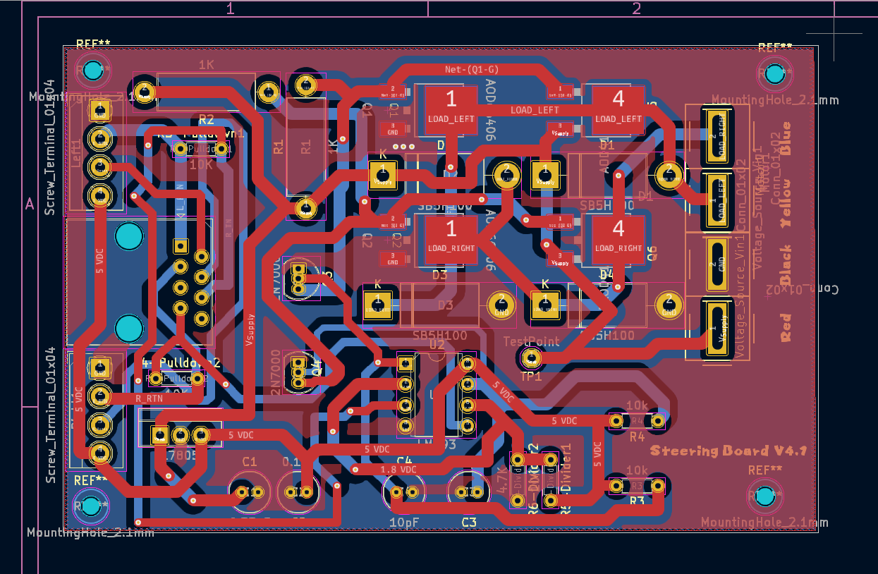
This is the PCB Diagram of the Steering Board Version 4.1. Ground Planes have been added to both sides of the board. The power traces have been increased from 1.27 mm to 1.5 mm to handle extra current, and the signal traces have been increased to .75-1 mm. Mounting Hole placement is not exact.
File history
Click on a date/time to view the file as it appeared at that time.
| Date/Time | Thumbnail | Dimensions | User | Comment | |
|---|---|---|---|---|---|
| current | 03:47, 17 March 2025 | | 1,245 × 814 (327 KB) | Elcanoadmin (talk | contribs) | This is the PCB Diagram of the Steering Board Version 4.1. Ground Planes have been added to both sides of the board. The power traces have been increased from 1.27 mm to 1.5 mm to handle extra current, and the signal traces have been increased to .75-1... |
- You cannot overwrite this file.
File usage
The following page uses this file: