Difference between revisions of "Low Level"
Elcanoadmin (talk | contribs) (→LowLevel v4.1 PCB) |
|||
| (46 intermediate revisions by 4 users not shown) | |||
| Line 1: | Line 1: | ||
| + | =LowLevel v4.1 PCB= | ||
| + | |||
| + | [[File:LowLevelv4_1_V2.jpg|600px|]] - 3D PCB Model on KiCAD [[File:Screenshot 2025-06-02 220036.png|600 px|]] - PCB Diagram on KiCAD | ||
| + | |||
| + | [[File:Screenshot 2025-06-07-232527.png|600 px|]] - Schematic 1/3 on KiCAD [[File:Screenshot 2025-06-07-232533.png|600 px|]] - Schematic 2/3 on KiCAD | ||
| + | |||
| + | [[File:Screenshot 2025-06-07-232539.png|600 px|]] - Schematic 3/3 on KiCAD | ||
| + | |||
| + | ==Overview== | ||
| + | This board that is to be fabricated by the next capstone team, builds from the Low Level V3.1 board which initially worked for the Arduino Mega, was reconfigured for the Arduino Due to behave like the Main DBW V4.0 board that was tested along with the Steering Board V4.1, connecting to the Arduino Due to using Pin Headers along with its ICSP pins the same way configured for the DBW V4.0 Board. There are two RJ45 connectors for the Throttle and Steering and a DB9 connector for CAN/UART signals, assuming the LLB is still the daughter board for the Arduino Due microcontroller board. This board also contains an in-house SD card mount for datalogging, thus possibly eliminating the need for the Arduino Shield. Brake Solenoid power traces are 2 mm, +12 volt is 1 mm, +5V is 0.5mm and the rest of the traces are 0.25 mm. | ||
| + | |||
| + | ==Theory of operation== | ||
| + | This board will control the motor, steering, and brake solenoids through a series of signal traces receiving data from the Arduino DUE and RC Controller that control the trike’s critical functions. 2A will flow to the brake solenoids while the rest of the signal traces that are quarter a millimeter thick (<1 mil) can handle up to 300 mA alongside the +3.3V traces, traces for +5V are 0.5 mm thick and 1 mm thick for +12V assuming they hold higher currents. The motor and steering will send and receive signals/power via individual RJ45 connectors. In LowLevel V3.1, there was a DB15 connector to connect between the low-level and the motor with twelve signals, only six of the high-priotity signals were kept (leaving the pins 5 and 8 for GND and +5V respectively) per the schematic diagram. | ||
| + | In LowLevel V3.1, there were two relays for the brake solenoids: one to power the solenoids on or off, and the other for switching between 24V pulse and 12V hold. To make it fully solid state, both relays were replaced with an NMOS low-side switch for the ON/OFF state and a dual PMOS high-side switch for 12/24V switching. When simulating the circuit on LTspice, the high-side switch PMOS that controls the 24V was always on regardless of the state of BRAKE_VOLT as shown in the table below. As a result, the 12/24 relay was maintained. | ||
| + | The highlighted red text shown that the PMOS switch was not functioning properly and the 12/24V relay was maintained for SOLENOID_POWER and SOLENOID_COMMON. | ||
| + | |||
| + | =Steering v4.1 Board= | ||
| + | [[File:SteeringBoard4.1.png|600px|]] [[File:SteeringBoard4.1_PCB.png|600px|]] | ||
| + | [[File:20250317_132530.jpg|1000px]] | ||
| + | |||
| + | ==Functionality:== | ||
| + | Power is supplied to this board from 12 VDC input on the red Anderson connector from the DBW board to power the H-bridge circuit and L7805 voltage regulator which will step down from 12 to 5 VDC to power the LM393 dual comparator. which controls the direction of the 12 VDC linear actuator which turns the trike. The H-Bridge contains two of each of the following MOSFETs: AOD4189 (PMOS), AOD66406 (NMOS), and 2N7000 (NMOS). The 2N7000 gate voltages will control the gates of the AOD's, allowing the actuator to turn the front wheels left or right. An LM393 Dual comparator is placed before the H-bridge with each of the comparator outputs going to the one of the two gates of the 2N7000s, the inverting inputs having a fixed reference voltage about 1.8 VDC, one non-inverting input connected to the left turn signal, and the other for the right turn signal with the remaining two pins connected to 5 VDC and GND respectively. there is an RJ45 LAN bus connector which receives signals from the Arduino Due (which in itself receives signals from an external RC infrared receiver), which will tell the LM393 comparator to control the H-bridge MOSFETs accordingly to the input steering direction. SB5H100 Schottky Diodes placed in flyback provide fast feedback times when the AOD4189 and AOD66406 MOSFETs switch on and off. The DBW v4.1 Board will be redesigned to fit the new steering board. | ||
| + | |||
| + | ==Main DBW v4.1 Board== | ||
| + | This board is a follow-up to the existing DBW v4 Board (refer to the DBW v4 Board below for its functionality), which will build on what the DBW v4 Board has accomplished. This board functions similarly to the LowLevel V4.1 | ||
| + | |||
| + | =LowLevel v4 PCB = | ||
| + | |||
| + | The V4 LowLevel PCB builds upon the V3.1 PCB. It still communicates over the CAN bus with the manual control or autonomous system from the receiver system. However, the new LLB is the daughter board for the Arduino Due microcontroller board. | ||
| + | |||
| + | == Functionality: == | ||
| + | |||
| + | * Uses binary control for steering as opposed to a PWM input | ||
| + | * LLB uses internal CAN bus module, removing the need for any external CAN modules | ||
| + | * Runs on 3.3V of power internally with power provided to the Arduino DUE through a 5v regulator on the DBW board | ||
| + | * Steering and throttle headers added to lower connector size | ||
| + | [[File:SteeringJ8.PNG|200px|Steering Connector J8]] [[File:MotorJ7.PNG|200px|Motor Connector J7]] | ||
| + | * RJ-45 adapter connected to steering pins | ||
| + | [[File:RJ45Adapter.jpg|300px|Steering header adapter]] | ||
| + | * Brakes use solenoids instead of actuators | ||
| + | [[File:YellowBrakes.jpg|300px|Solenoid Brakes]] | ||
| + | |||
| + | * Creates file for outputting date and stores it in SD card | ||
| + | * PCF8523 RTC calculates and stores the following using system time: | ||
| + | ** Milliseconds since compile time | ||
| + | ** Epoch time | ||
| + | ** Date (YYYY/MM/DD) | ||
| + | ** Day of the week | ||
| + | ** Standard time (HH:MM:SS) (AM/PM) | ||
| + | ==DBW v4 Board== | ||
| + | [[File:DBWv4Board.jpg|300px|]] [[File:DBWv4Layout.png|600px|]] | ||
| + | |||
| + | Power is supplied to the board through the 12 V input on the screw terminal closest to the Arduino DUE and steps this down to 5V and 3.3V through its voltage regulators. The 12V input also supplies the solenoid brakes and to the steering board. CAN L and H are also accessible on this screw terminal or can be connected to from the CAN header that is above the steering header. DBW v4 uses level shifters to convert the peripheral voltage 0-5V to 0-3.3 V which the Arduino DUE is able to operate at. The advantage of this is that the Arduino DUE's internal CAN bus can be used instead of an external module with the trade off being the added complexity of the level shifters. An improvement that can be made is to replace 5 V peripherals with 3.3 V peripherals to reduce the amount of level shifters. This is relevant to the current angle sensors using 5 volts and they can be easily converted to using 3.3 V. The brake relays on the DBW v4 board are setup backwards with 24 V being sent to the brakes by default and this needs to be fixed in future iterations. Other future improvements are the addition of RJ-45 connectors that will eliminate the need for a converter box to be used. Problems with the 5V and 3.3V regulator have been found with the 3.3V regulator failing on at least 3 boards. The 12 volt input is directly connected to multiple IC's and has a high risk of damage if there is a voltage spike created from the connected power supply to the board. | ||
| + | |||
| + | |||
=LowLevel v3.1 PCB = | =LowLevel v3.1 PCB = | ||
| Line 5: | Line 60: | ||
==Functionality: == | ==Functionality: == | ||
| − | * The LowLevel Board (LLB) is a daughter board (shield) for an Arduino Mega microcontroller. It implements drive-by-wire, turning a trike into a CAN-bus based vehicle compatible with commercial self-driving equipment. The LLB communicates over the CAN bus with | + | * The LowLevel Board (LLB) is a daughter board (shield) for an Arduino Mega microcontroller. It has been renamed "Drive-By-Wire". It implements drive-by-wire, turning a trike into a CAN-bus based vehicle compatible with commercial self-driving equipment. The LLB communicates over the CAN bus with the higher-level autonomous system or manual control from the receiver system. It directly manages the actuators: the throttle to the motor, the turning servo, and the brakes. |
| Line 17: | Line 72: | ||
*** Digital outputs for activating reverse and regenerative braking. | *** Digital outputs for activating reverse and regenerative braking. | ||
*** PWM output for PWM-operated braking (no longer used) | *** PWM output for PWM-operated braking (no longer used) | ||
| − | *** Analog inputs for hall sensor feedback from motor controllers supporting this feature. These inputs are NOT | + | *** Analog inputs for hall sensor feedback from motor controllers supporting this feature. These inputs are NOT 5V SAFE. They absolutely require external supporting circuitry. |
*** A few spare connections for future expandability, such as a second DAC output and one digital GPIO. | *** A few spare connections for future expandability, such as a second DAC output and one digital GPIO. | ||
| + | |||
| + | DETAILS > [[DB15M]] | ||
| + | |||
** Steering Header (RJ45): | ** Steering Header (RJ45): | ||
*** Two sets of pins to support analog potentiometers (5v, signal input, ground) giving angle of front wheels | *** Two sets of pins to support analog potentiometers (5v, signal input, ground) giving angle of front wheels | ||
| Line 30: | Line 88: | ||
* The LowLevel runs on 5V power, and provides outputs for sensors. Note that the Arduino Mega 2560's regulator has a fairly low current limit, and should not be used for any significant current supply. The Arduino's DC input jack accepts 12V, and its USB port may be connected to a typical USB power supply. The 12V is provided by a DC-DC converter from the main battery (36 to 50V). | * The LowLevel runs on 5V power, and provides outputs for sensors. Note that the Arduino Mega 2560's regulator has a fairly low current limit, and should not be used for any significant current supply. The Arduino's DC input jack accepts 12V, and its USB port may be connected to a typical USB power supply. The 12V is provided by a DC-DC converter from the main battery (36 to 50V). | ||
| + | ==Image: [[File:LowLevel.JPG|1000px]] == | ||
| + | |||
| + | |||
| + | NEXT > [[High Level]] | ||
=LowLevel v2.1 PCB = | =LowLevel v2.1 PCB = | ||
| + | |||
| + | |||
==Functionality: == | ==Functionality: == | ||
| − | * | + | * Version 2.1 used UART serial connections to other boards instead of the CAN bus. It interprets messages from higher-level autonomous systems or manual controls (RC, joystick). It directly manages the state of the actuators; the hub motor, the turning servo, and the brakes. |
| − | |||
* Depending on the current firmware or operating mode, motion directives are received on one of three interfaces; | * Depending on the current firmware or operating mode, motion directives are received on one of three interfaces; | ||
| Line 47: | Line 110: | ||
** X2 Cruise (DB-25F) - [[ElcanoSerial]] messages from High Level. | ** X2 Cruise (DB-25F) - [[ElcanoSerial]] messages from High Level. | ||
** X3 Motor ([[DB15M | DB-15M]]): Analog voltage (0,4v) output hub motor. | ** X3 Motor ([[DB15M | DB-15M]]): Analog voltage (0,4v) output hub motor. | ||
| − | ** X1/X5 Turn Sensors (RJ45): SPI wheel angle sensor digital inputs. ( | + | ** X1/X5 Turn Sensors (RJ45): SPI wheel angle sensor digital inputs. (Digital urn sensors were never implemented.) |
| − | ** X4 (ODO): Cyclometer (reed switch) input jack. Board layout was incorrect. This signal | + | ** X4 (ODO): Cyclometer (reed switch) input jack. Board layout was incorrect. This signal needs to be jumpered to Arduino pin D2. |
| − | ** JP9 (8 pin): Joystick analog input signals. | + | ** JP9 (8 pin): Joystick analog input signals. |
| − | ** JP12 (3 pin): Pulse output signal to steer. | + | ** JP12 (3 pin): Pulse output signal to steer. |
** JP11 (3 pin): Pulse output signal to apply main brakes. (No longer used) | ** JP11 (3 pin): Pulse output signal to apply main brakes. (No longer used) | ||
** JP5 (4 pin): Left wheel angle sensor analog input. (Little used since it covers 360 degrees and is less accurate) | ** JP5 (4 pin): Left wheel angle sensor analog input. (Little used since it covers 360 degrees and is less accurate) | ||
| Line 58: | Line 121: | ||
** Removes the ElcanoSerial connection and the DB-25F. | ** Removes the ElcanoSerial connection and the DB-25F. | ||
** Removes JP9, joystick analog inputs. | ** Removes JP9, joystick analog inputs. | ||
| − | ** Removes headers | + | ** Removes headers used to interface the RC receiver. |
| − | ** Adds one CANbus interface on a DE-9F socket. For legacy compatibility | + | ** Adds one CANbus interface on a DE-9F socket. For legacy compatibility UART serial is be available on this interface as well. |
| + | |||
| + | |||
| + | =LowLevel v1.0 PCB = | ||
| + | |||
| + | * The first version of the LLB was called MegaShieldDB. It had similar functionality, but different connectors. It had five DB connectors. | ||
| + | |||
| − | + | NEXT > [[High Level]] | |
Latest revision as of 05:13, 9 June 2025
Contents
LowLevel v4.1 PCB
 - 3D PCB Model on KiCAD
  - PCB Diagram on KiCAD
 - Schematic 1/3 on KiCAD
  - Schematic 2/3 on KiCAD
 - Schematic 3/3 on KiCAD
Overview
This board that is to be fabricated by the next capstone team, builds from the Low Level V3.1 board which initially worked for the Arduino Mega, was reconfigured for the Arduino Due to behave like the Main DBW V4.0 board that was tested along with the Steering Board V4.1, connecting to the Arduino Due to using Pin Headers along with its ICSP pins the same way configured for the DBW V4.0 Board. There are two RJ45 connectors for the Throttle and Steering and a DB9 connector for CAN/UART signals, assuming the LLB is still the daughter board for the Arduino Due microcontroller board. This board also contains an in-house SD card mount for datalogging, thus possibly eliminating the need for the Arduino Shield. Brake Solenoid power traces are 2 mm, +12 volt is 1 mm, +5V is 0.5mm and the rest of the traces are 0.25 mm.
Theory of operation
This board will control the motor, steering, and brake solenoids through a series of signal traces receiving data from the Arduino DUE and RC Controller that control the trike’s critical functions. 2A will flow to the brake solenoids while the rest of the signal traces that are quarter a millimeter thick (<1 mil) can handle up to 300 mA alongside the +3.3V traces, traces for +5V are 0.5 mm thick and 1 mm thick for +12V assuming they hold higher currents. The motor and steering will send and receive signals/power via individual RJ45 connectors. In LowLevel V3.1, there was a DB15 connector to connect between the low-level and the motor with twelve signals, only six of the high-priotity signals were kept (leaving the pins 5 and 8 for GND and +5V respectively) per the schematic diagram. In LowLevel V3.1, there were two relays for the brake solenoids: one to power the solenoids on or off, and the other for switching between 24V pulse and 12V hold. To make it fully solid state, both relays were replaced with an NMOS low-side switch for the ON/OFF state and a dual PMOS high-side switch for 12/24V switching. When simulating the circuit on LTspice, the high-side switch PMOS that controls the 24V was always on regardless of the state of BRAKE_VOLT as shown in the table below. As a result, the 12/24 relay was maintained. The highlighted red text shown that the PMOS switch was not functioning properly and the 12/24V relay was maintained for SOLENOID_POWER and SOLENOID_COMMON.
Steering v4.1 Board


Functionality:
Power is supplied to this board from 12 VDC input on the red Anderson connector from the DBW board to power the H-bridge circuit and L7805 voltage regulator which will step down from 12 to 5 VDC to power the LM393 dual comparator. which controls the direction of the 12 VDC linear actuator which turns the trike. The H-Bridge contains two of each of the following MOSFETs: AOD4189 (PMOS), AOD66406 (NMOS), and 2N7000 (NMOS). The 2N7000 gate voltages will control the gates of the AOD's, allowing the actuator to turn the front wheels left or right. An LM393 Dual comparator is placed before the H-bridge with each of the comparator outputs going to the one of the two gates of the 2N7000s, the inverting inputs having a fixed reference voltage about 1.8 VDC, one non-inverting input connected to the left turn signal, and the other for the right turn signal with the remaining two pins connected to 5 VDC and GND respectively. there is an RJ45 LAN bus connector which receives signals from the Arduino Due (which in itself receives signals from an external RC infrared receiver), which will tell the LM393 comparator to control the H-bridge MOSFETs accordingly to the input steering direction. SB5H100 Schottky Diodes placed in flyback provide fast feedback times when the AOD4189 and AOD66406 MOSFETs switch on and off. The DBW v4.1 Board will be redesigned to fit the new steering board.
Main DBW v4.1 Board
This board is a follow-up to the existing DBW v4 Board (refer to the DBW v4 Board below for its functionality), which will build on what the DBW v4 Board has accomplished. This board functions similarly to the LowLevel V4.1
LowLevel v4 PCB
The V4 LowLevel PCB builds upon the V3.1 PCB. It still communicates over the CAN bus with the manual control or autonomous system from the receiver system. However, the new LLB is the daughter board for the Arduino Due microcontroller board.
Functionality:
- Uses binary control for steering as opposed to a PWM input
- LLB uses internal CAN bus module, removing the need for any external CAN modules
- Runs on 3.3V of power internally with power provided to the Arduino DUE through a 5v regulator on the DBW board
- Steering and throttle headers added to lower connector size


- RJ-45 adapter connected to steering pins

- Brakes use solenoids instead of actuators

- Creates file for outputting date and stores it in SD card
- PCF8523 RTC calculates and stores the following using system time:
- Milliseconds since compile time
- Epoch time
- Date (YYYY/MM/DD)
- Day of the week
- Standard time (HH:MM:SS) (AM/PM)
DBW v4 Board


Power is supplied to the board through the 12 V input on the screw terminal closest to the Arduino DUE and steps this down to 5V and 3.3V through its voltage regulators. The 12V input also supplies the solenoid brakes and to the steering board. CAN L and H are also accessible on this screw terminal or can be connected to from the CAN header that is above the steering header. DBW v4 uses level shifters to convert the peripheral voltage 0-5V to 0-3.3 V which the Arduino DUE is able to operate at. The advantage of this is that the Arduino DUE's internal CAN bus can be used instead of an external module with the trade off being the added complexity of the level shifters. An improvement that can be made is to replace 5 V peripherals with 3.3 V peripherals to reduce the amount of level shifters. This is relevant to the current angle sensors using 5 volts and they can be easily converted to using 3.3 V. The brake relays on the DBW v4 board are setup backwards with 24 V being sent to the brakes by default and this needs to be fixed in future iterations. Other future improvements are the addition of RJ-45 connectors that will eliminate the need for a converter box to be used. Problems with the 5V and 3.3V regulator have been found with the 3.3V regulator failing on at least 3 boards. The 12 volt input is directly connected to multiple IC's and has a high risk of damage if there is a voltage spike created from the connected power supply to the board.
LowLevel v3.1 PCB
Functionality:
- The LowLevel Board (LLB) is a daughter board (shield) for an Arduino Mega microcontroller. It has been renamed "Drive-By-Wire". It implements drive-by-wire, turning a trike into a CAN-bus based vehicle compatible with commercial self-driving equipment. The LLB communicates over the CAN bus with the higher-level autonomous system or manual control from the receiver system. It directly manages the actuators: the throttle to the motor, the turning servo, and the brakes.
- Motion directives are received on a CAN bus interface, processed, and articulated.
- System status (turn angle, wheel linear velocity) is reported back to CAN bus.
- LLB v3.x has the following interfaces:
- One CANbus channel on two connectors; a DB9-M and a three-pin screw terminal. The board includes a 120 ohm terminating resistor.
- X3 Motor (DB-15M): Interface to E-bike controller
- Analog voltage (approximately 0v to 4v) output to hub motor throttle
- Digital outputs for activating reverse and regenerative braking.
- PWM output for PWM-operated braking (no longer used)
- Analog inputs for hall sensor feedback from motor controllers supporting this feature. These inputs are NOT 5V SAFE. They absolutely require external supporting circuitry.
- A few spare connections for future expandability, such as a second DAC output and one digital GPIO.
DETAILS > DB15M
- Steering Header (RJ45):
- Two sets of pins to support analog potentiometers (5v, signal input, ground) giving angle of front wheels
- One PWM output (with its own ground) to drive the steering actuator.
- This cable is broken out into its component signals using an RJ45 patch jack, mounted near the steering actuator.
- X4 (ODO): Cyclometer (reed switch) input jack. This is pulled high by default, and brought low when the magnet passes the sensor.
- High current pluggable terminal for solenoid brakes:
- Connections for ground, 12v, and 24v.
- Two relay outputs to solenoids: on/off and 12/24V.
- Steering Header (RJ45):
- The LowLevel runs on 5V power, and provides outputs for sensors. Note that the Arduino Mega 2560's regulator has a fairly low current limit, and should not be used for any significant current supply. The Arduino's DC input jack accepts 12V, and its USB port may be connected to a typical USB power supply. The 12V is provided by a DC-DC converter from the main battery (36 to 50V).
Image: 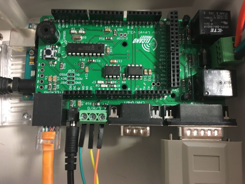

NEXT > High Level
LowLevel v2.1 PCB
Functionality:
- Version 2.1 used UART serial connections to other boards instead of the CAN bus. It interprets messages from higher-level autonomous systems or manual controls (RC, joystick). It directly manages the state of the actuators; the hub motor, the turning servo, and the brakes.
- Depending on the current firmware or operating mode, motion directives are received on one of three interfaces;
- ElcanoSerial from the combined C3/ C4/ C6 High Level board
- RC receiver
- Manual Joystick
- LLB v2.x has the following low-level interfaces:
- X2 Cruise (DB-25F) - ElcanoSerial messages from High Level.
- X3 Motor ( DB-15M): Analog voltage (0,4v) output hub motor.
- X1/X5 Turn Sensors (RJ45): SPI wheel angle sensor digital inputs. (Digital urn sensors were never implemented.)
- X4 (ODO): Cyclometer (reed switch) input jack. Board layout was incorrect. This signal needs to be jumpered to Arduino pin D2.
- JP9 (8 pin): Joystick analog input signals.
- JP12 (3 pin): Pulse output signal to steer.
- JP11 (3 pin): Pulse output signal to apply main brakes. (No longer used)
- JP5 (4 pin): Left wheel angle sensor analog input. (Little used since it covers 360 degrees and is less accurate)
- JP6 (4 pin): Right wheel angle sensor analog input. (Trike prefer this, since it is +/- 30 degrees, and more accurate)
- LLB v3.x makes significant wiring changes:
- Removes the ElcanoSerial connection and the DB-25F.
- Removes JP9, joystick analog inputs.
- Removes headers used to interface the RC receiver.
- Adds one CANbus interface on a DE-9F socket. For legacy compatibility UART serial is be available on this interface as well.
LowLevel v1.0 PCB
- The first version of the LLB was called MegaShieldDB. It had similar functionality, but different connectors. It had five DB connectors.
NEXT > High Level