Difference between revisions of "Power System"
(→Motor Driver Board August 2025) |
(→Voltage Regulator) |
||
| Line 99: | Line 99: | ||
=== Voltage Regulator === | === Voltage Regulator === | ||
| + | [[File:Motor Driver Voltage Regulator.png]] | ||
The voltage regulator takes in 12 Volts from the battery and outputs 5 Volts, which is labeled as VCC through the system. The 5 volt rail powers the smaller IC’s on the board which need a lower voltage to operate. | The voltage regulator takes in 12 Volts from the battery and outputs 5 Volts, which is labeled as VCC through the system. The 5 volt rail powers the smaller IC’s on the board which need a lower voltage to operate. | ||
Revision as of 21:08, 24 August 2025
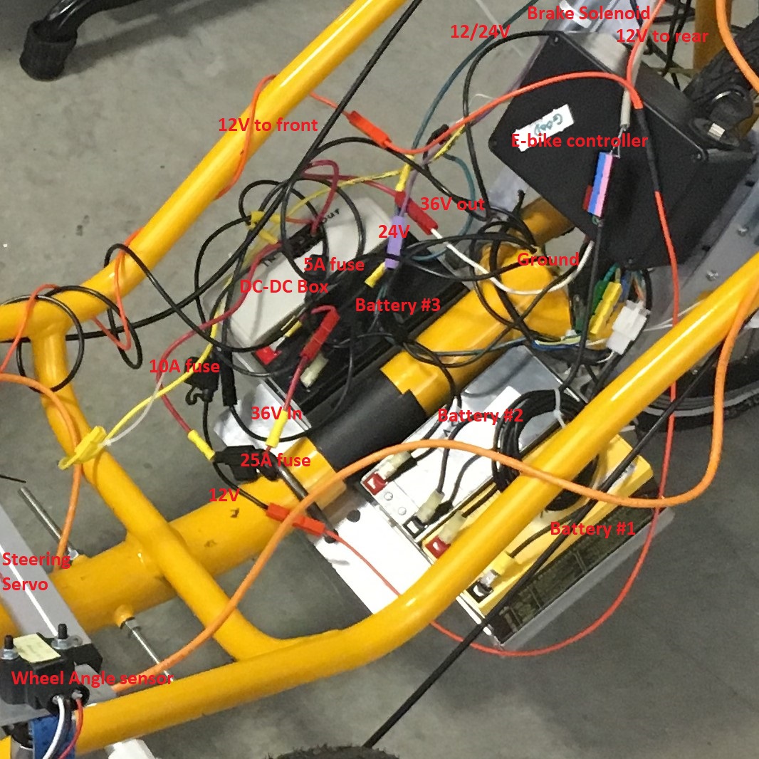
The Elcano power supply is a 36V battery on the Catrike recumbents or a 48V supply on the ELF. The picture shows three 12V lead-acid batteries connected in series to provide 36V. The fourth box in the top of the picture is a plastic case that houses a circuit board and two DC-DC converters. The converters output a 12V supply and a 24V supply. All power lines are color-coded with the right color wire when possible and with the right color Anderson connectors. The power lines are:
- Ground: Black
- Pink: 5V (not commonly used between modules)
- Orange: 12V
The steering servo runs on 12V.
Brakes are held on with 12V.
All Arduinos have a Vin pin that can take 12V. The Arduino internally converts the voltage to 5V and 3.3V.
The four-wire CAN connection consists of CAN hi, CAN lo, Ground, and 12V. This connection powers the Raspberry Pi, Receiver board and Scanse Sweep board.
- Purple: 24V
Used to apply the brakes.
- Green: Either 12V or 24V
This is the power line to the brake solenoids. It is initially 24V to apply the brake, then reduced to 12V to hold the brake on.
- Red: 36V or 48V power
Contents
Power System Pre-2024
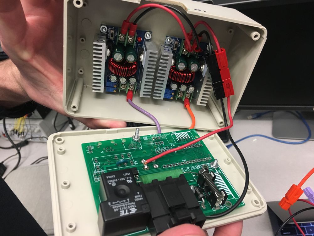
Main power goes to the E-Bike controller, which converts DC power to three phase AC to drive the electric motor. The circuit board inside the box (shown in the picture below) with the DC-DC converters does some conditioning on the main power before sending it on to the E-Bike controller. The signal conditioning board has been called the PowerOn board. It initially had three functions:
1. Provide a power-on circuit that the Kelly e-bike controllers need. It has a large resistor between the 36V input line and 36V output line. When the switch is thrown, a relay bypasses the resistor.
2. Signal conditioning on phase signals from electric motor to give a fine resolution of vehicle speed.
3. An Arduino Micro applied the correct PWM signal to the brakes when E-stop was triggered. The Arduino is no longer used, since PWM is no longer used to control brakes.
The PowerOn board presently in use implements only the first function. The board is cut and jumpered so that the DPST switch also turns the 12V and 24V lines on/off. The fuse is bypassed by a bolt. The fuse was originally 2 Amps, and intended for the signal portion of the 36V line that drives the e-bike controller. (The main 36V line goes the the electric motor and is fused for 25A). The 12V line is fused for 10A and the 24V line for 5A. Since both of these lines now go through the fuse on the board, that fuse is too small and is redundant.
Power System Summer 2024
The Current power system takes 36 V from the batteries and steps it down to 24 V in one converter and then to 12 V in a second converter. Grounds are all connected together and fuses are included for all DC-DC converters. All the voltage outputs are connected on a connector box where wires can be connected to power peripherals at 12 or 24 volts. Problems have been experienced with voltage fluctuations based on current draw
E-bike controller
The Kelly E-bike controller is power by 36V directly connected to the batteries and it receives inputs 0-5V from the DBW board.
DC-DC converters
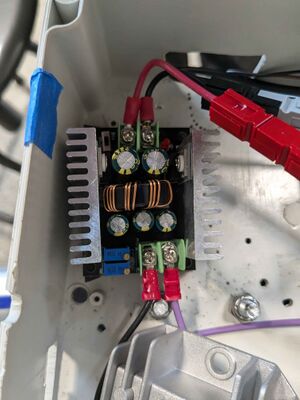
36-24V converter
Part link 36-24 V DC regulator
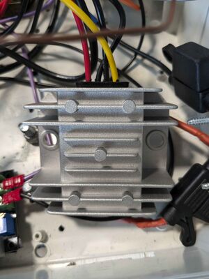
24-12V converter
Part link 24-12 V DC regulator
Current Peripherals being powered
- Steering board 12V
- Kelly E-bike controller 36V
- Solenoid Brakes 12-24V
- DBW board 12V
Motor Driver Board August 2025
Overview
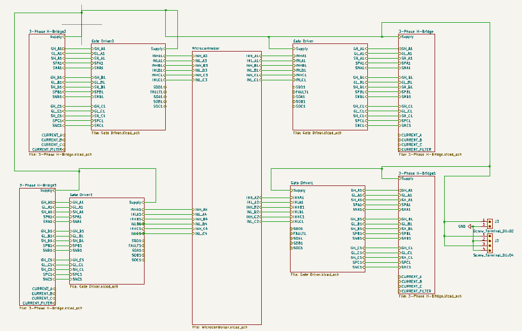
There are 4 identical motor controller systems, which are made up of a gate driver and a 3-phase H-Bridge. All of them are all attached to the central microcontroller, a NUCLEO L476RG, arranged in a way the optimized trace distance. Each motor controller is attached to its own wheel and provides feedback to the microcontroller to aid it in determining what new speed the wheels need to be set at. This is done via hall effect sensors, which are not implemented on the schematic due to being directly connected with wires in this iteration. In addition, there are connections for our additional systems, such as the Jetson Nano, to be powered through an external buck regulator. This can be seen on the bottom right corner with 2 and 4 hole connectors connected to the battery supply and ground.
Microcontroller
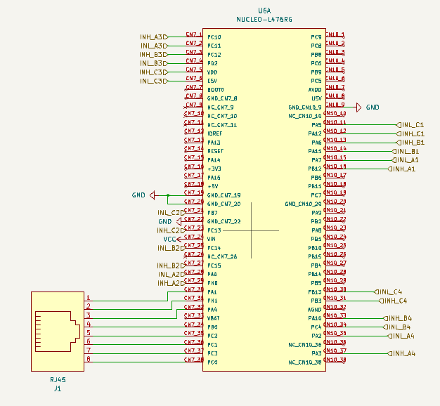
The RJ45 connector inputs 8 signals from the Drive-By-Wire board into the microcontroller, which gives the throttle signals, and also takes in current speed from hall effect sensors for each wheel. These inputs are read and processed by the microcontroller, which then outputs signals that determine the speed and direction that are needed. The relevant signals necessary to achieve this are then fed to the Gate Drivers, for a total of 6 outputs for each Gate Driver. Each set of outputs has been placed to optimize distance to the Gate Drivers. The MCU is powered through the VCC pin which operates at 5 volts, taken off of a 5-volt buck converter. Future signals may need to be added later on, depending on what full testing reveals, as the system this is based on, VESC, has feedback signals from the Gate Drivers. These should all ideally fit on to the current MCU if needed, but each wheel maybe need is own board if there is no more room.
Gate Driver
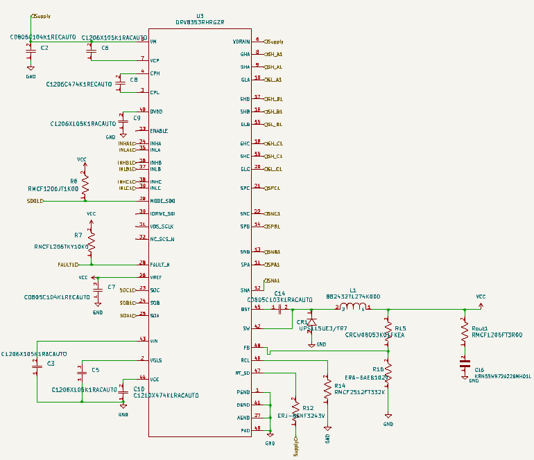
The Gate Driver is both supplied by the battery and off of the 5 volts regulator. It takes in the output signals from the microcontroller and amplifies them for use by the 3-Phase H-Bridge. It also takes in feedback from the H-Bridge’s bottom MOSFETS sensor resistors to aid in correctly amplifying the input signals into the MOSFETs.
3-Phase H-Bridge
The H-Bridge is controlled by the Gate Driver’s outputs to the MOSFETs’ gate pin, and by the 12 Volt battery supply, which firstly determines the operation mode the MOSFETs should be in. In addition, the output signals determine the speed via the frequency they are being sent at. This combined determines if the ATV needs to go forwards or backwards, and how fast it needs to do so. The sensor resistors attached to the bottom MOSFETs again provide feedback to the Gate Driver, and there are analog switches which have not been implemented into the overall design yet.
Voltage Regulator
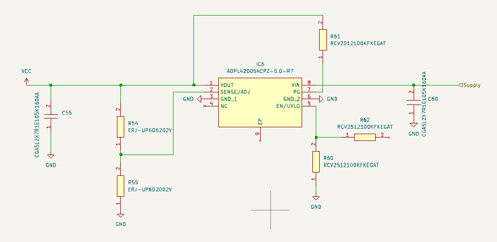
The voltage regulator takes in 12 Volts from the battery and outputs 5 Volts, which is labeled as VCC through the system. The 5 volt rail powers the smaller IC’s on the board which need a lower voltage to operate.
NEXT > Low Level
